Versions Compared

Key

  • This line was added.
  • This line was removed.
  • Formatting was changed.

Table of Contents

Table of Contents

Scope

This page describes the creation of a network example - or instance model. It should guide the discussion about network creation as composite of cloudified and physical network functions for different technologies (RAN, Transport, Core and Cloud). 

Several formats of the same network instance are used to describe the network in an abstract way. 

For the description of the network topology - the association between the network functions - the ietf-network-topology model according to https://datatracker.ietf.org/doc/html/rfc8345 is used 

Radio Access Network

The Radio Access Network follows the O-RAN Architecture. 

5G Core

The most simplistic way is to create only one 5G-Core instance for the network.  The description of interfaces between the RAN and the 5G Core, only one UPF and only one AMF will be instantiated and added to the network topology. 

Transport

Packet, optical and wireless transport nodes are not part at this point in time, but may by added later. Fronthaul gateways might be an exception to this view. However, the topology model is abstact enough, so that another network function type does not make a different to software implementation. 

Cloud

There needs to be a difference between cloud resources (resource pools) where more centralized functions are deployed and where cloudified edge function are deployed. The topology model needs to support topology nodes representing resource pools where cloudified network functions can be deployed.

Cell Study

A cell (3GPP:NrCellDu) is the thing which offers mobility services to user equipment (3GPP:UE). The cell offers coverage over a particular area.

The cell geographical polygon can be very complex in the reality, because it depend on a lot of technical parameters and the geographical topology.

For simplification, it is assumed that cells on a tower cover a hexagon around the tower.


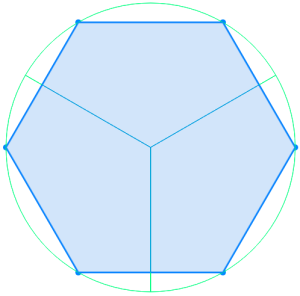
Number of cells per tower

The figure on the left shows 3 Cells covering the area around a cell tower in the middle. The hexagon orientation is 'flat' and the azimuth 0 (north) represents the center of the cell. 

The radius around the cell tower depends several parameters and conditions. One important parameter is the transmit power of the cell. Please keep in mind that for coverage also the transmit power of the UE is important - for simplification it is assumed that all kind of UEs within the cell can communicate thought this cell. 


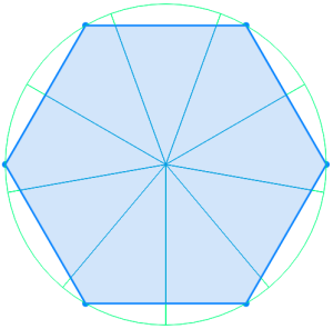
In some cases the number of souring cells can be increased based on the hardware capabilities. The cell angel (here 60°) is just a parameter to the network design. In our example the value 120° like shown in the figure above will be used. 
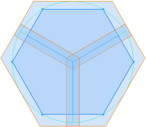

Handover area

In relative there are "handover" areas - a geographical area where a UE has the possibility to chose between two cells. For the planned network we simply in crease the size of the cell by a factor. The figure on the left shows the cell coverage using the factor +30%. 


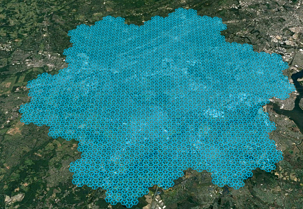
Hexagon grid on a map

After the details of the cell shapes are defined and following the concept and rules of a hexagon grid, we can calulate a 5G network and place it on a map.


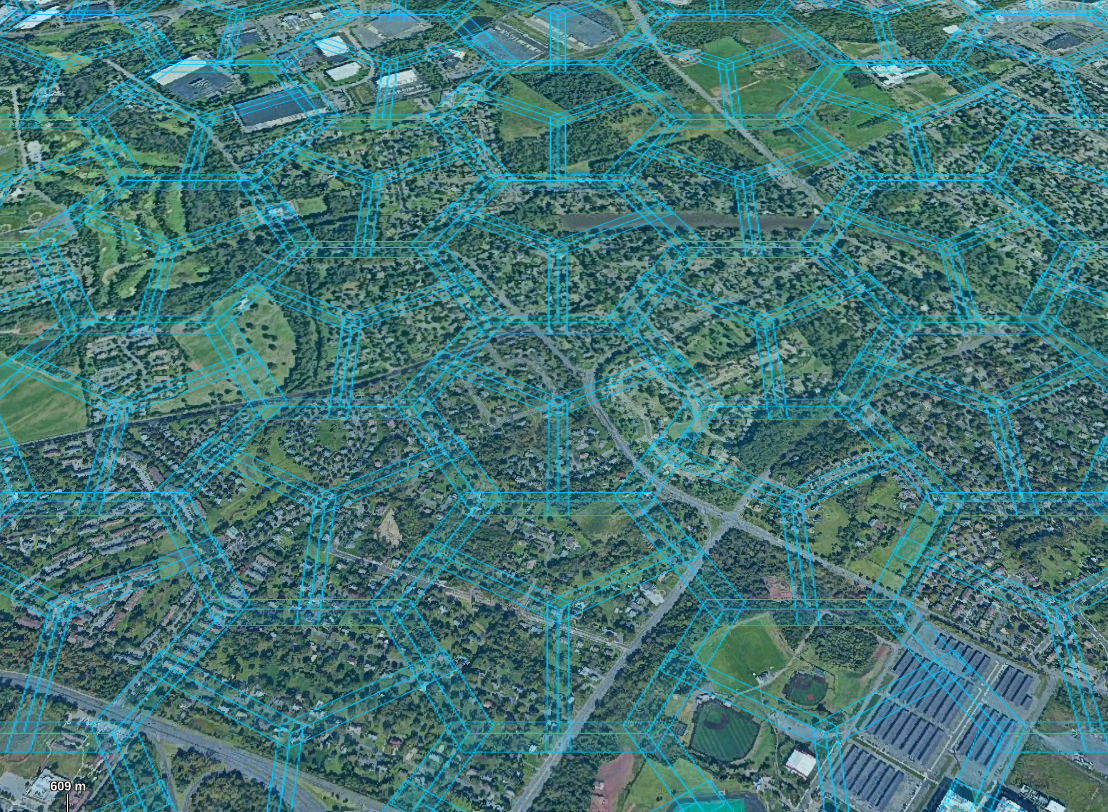
In a more detailed view, the handover areas and the the positions for towers can be seen. 


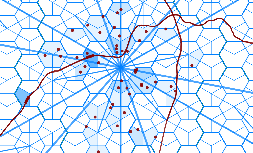
User equipment on the network

The same hexagon gird above represented as SVG offers some nice effects, when modeling the dynamic movement of UEs maybe also  following railways paths. Each UE represented as a red dot requires different thought put (capacity) through the 5G network. The cell color can be us as indicated of the utilization of the cell compared to the maximal capacity of the cell.